這篇文章 5g Software Architecture 最早出現於 AEWIN。
]]>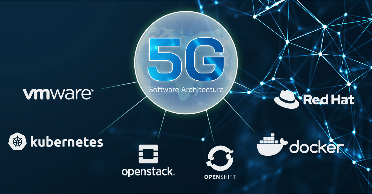
5G Software Architecture
Previously, we’ve looked at the hardware requirements of 5G. This week, we will take a look at the software infrastructure targeted for 5G deployments. There are published concepts and specifications by vendors like Intel and standards organizations such as O-RAN and OpenRAN. However these concepts are a bit nebulous, and these concepts may not work with all the potential use cases of future 5G deployment. Many of these concept and specs are focused on carrier grade deployments, and there are many potential 5G customers outside of telecom applications such as manufacturing campus or huge vessels.
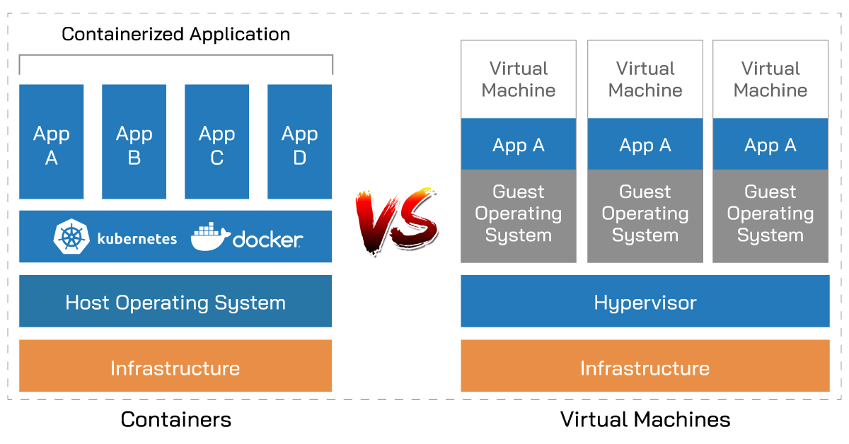
There is a common trend among the different designs: the software stack is going away from bare-metal and moving towards virtualization or containerized software stack with centralized management software to easily deploy and manage all the nodes. Solutions from RedHat, VMware, and other leading software vendors all coming with VM and container management solution that can host customized 5G software stack. Intel is in on the action as well with the virtualized FlexRAN solution. The aim of these software stack is chaining together a cohesive stack of centrally managed software.
One of the leading VM software suite vendor, VMware, is integrating container support into their vSphere virtualization platform, showing how the container concept is catching on and can no longer be ignored by virtualization specialists. Red Hat, another juggernaut in enterprise OS and virtualization platforms introduced OpenShift container management platform. Even Microsoft got in on the container band wagon, integrating OpenShift into their Azure hybrid cloud computing platform.
For those with limited scale or budgets, Docker containers deployed through Kubernetes orchestration system are available freely. These open source alternatives don’t give up on features. The biggest difference, as usual in the open source landscape, is support. Professional support is available from the boxed software vendors, where as in open source alternative you will rely on documentations and community support for debugging issues that may arise.
The software stack is paramount moving away from proprietary vendor solutions and towards open standards software and hardware. This will bring down the hurdle for enterprises and business who wish to build private 5G networks for their internal needs. This allows open competition on the hardware front. It is great for hardware vendors, despite the increased competition. It forces vendors to innovate to attract customers as well as building on their own vision of 5G hardware to carve out specific niche markets. One size fits none and through the competition, it will allow customers to find hardware that fits their exact needs and choose software that will integrate well into their existing software infrastructure. What we’re envisioning is enterprises will choose to run a base OS they’re familiar with, such as RHEL or CentOS, then run a vendor provided KVM or, more likely, containers that bundles all the software required. Software and hardware vendors will need to work closely to provide application optimized solutions.
Thanks for joining us again for another look at 5G. We’ll revisit this topic as industry trends becomes more concrete. All-in-one small-cell looks like the next hot 5G topic, and we’ll definitely look deeper into that in a future blog post.
這篇文章 5g Software Architecture 最早出現於 AEWIN。
]]>這篇文章 Redfish-Open Industry Standard Protocol 最早出現於 AEWIN。
]]>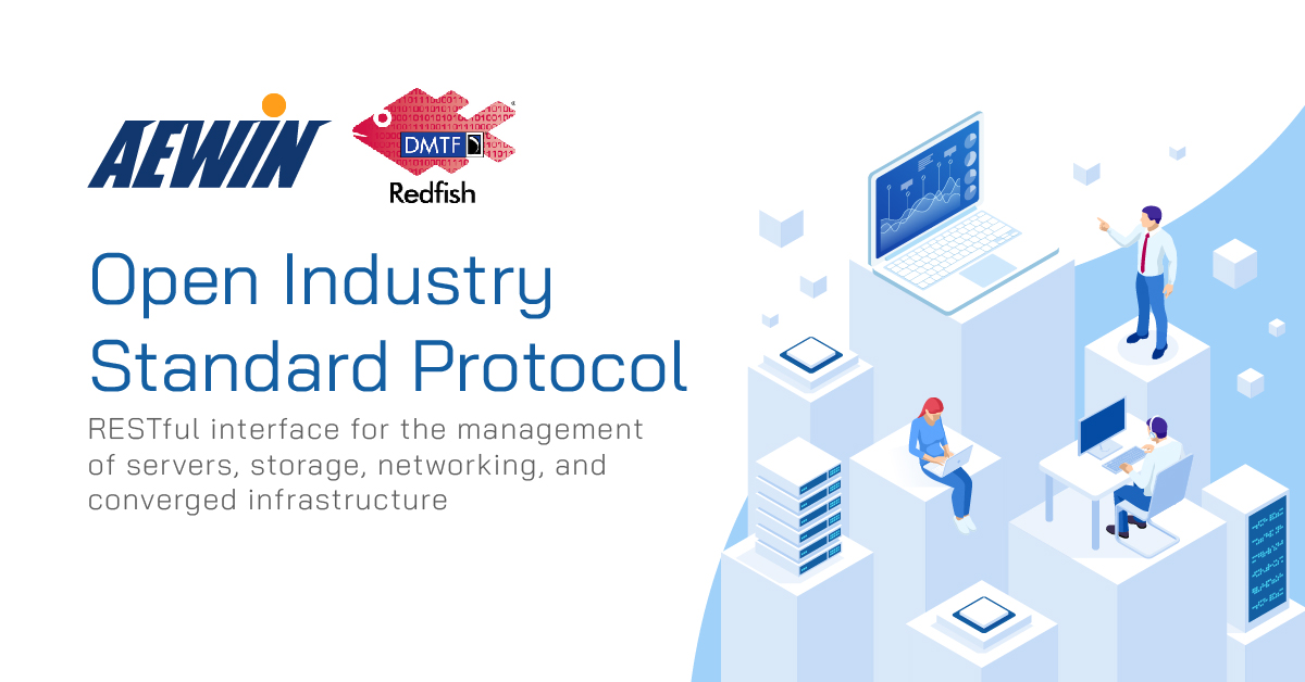
System management traditionally had relied on the venerable IPMI protocol standard established in 1998. Since then, there has been considerable advancement in technology and command-line tools fell out of favor as compared to modernized GUI that can visualize the process into an intuitive interface. Enter the Redfish specifications published by DMTF (Distributed Management Task Force).
Redfish is an open industry standard protocol aiming to utilize modern web standards capable of managing large scale deployment of servers today. This standard utilizes the common RESTFUL web interface as well as the JSON data format. These are common standards utilized on the internet, easing the development and compatibility of the management utilities. These web technologies also enable server management and monitoring through common web browsers, streamlining the process. Since Redfish is designed in the modern era, there are significantly better integration of system BIOS and on-board BMC.
Ultimately, Redfish allows server administrators to control large scale deployment of servers worldwide. The current IPMI tools are not friendly to automations and became fragmented as vendors keep building on their own proprietary IPMI commands that are not interoperable and complicated to manage in a mixed vendor environment. Through standardizing on Redfish, future tools will allow a single administration panel to work across different server brands as long as it supports the Redfish standard. This also opens the possibility of 3rd party management tools. Through common scripting languages like Python and PowerShell, administrators can automate management, updating, and deployment through familiar tools.
AEWIN is phasing in Redfish support across many different platforms. AEWIN’s recently announced 1932 and 1937, based on the latest processors from Intel and AMD respectively, are among the first to support this versatile new standard.
 |
SCB-1932 Network Appliance | Edge computing server ●Support Dual 3nd Gen Intel® Xeon® Scalable Processors, LGA4189 ●16x DDR4 3200MHz memory ●8x PCIe x8 for Network Expansion Module ●2x 2.5” HDD/SSD, 2x M.2 2280 & 1x m-SATA ●Support OT006A/B Trusted Secure Boot modules |
|
SCB-1937 Network Appliance | Edge computing server ●Support Dual AMD® EPYC  7003/7002 Series Processors, LGA4094 7003/7002 Series Processors, LGA4094●16x DDR4 3200MHz memory ●8x PCIe x8 for Network Expansion Module ●2x 2.5” HDD/SSD, 2x M.2 2280 & 1x m-SATA ●Support OT004A Trusted Secure Boot modules |
這篇文章 Redfish-Open Industry Standard Protocol 最早出現於 AEWIN。
]]>這篇文章 What is Edge AI?How about Edge AI applications? 最早出現於 AEWIN。
]]>
There are many definitions of the Edge, but in general Edge can be defined as on-premises systems or forwardly deployed servers at edge cloud to service a building, neighborhood, or city block. The proximity of these servers to the users alleviates the network traffic and latencies required to traverse to the datacenter.
More:The solutions about Edge AI
Edge AI will continue to be the trend as the next logical step of digital transformation of businesses, as more office tasks are augmented or replaced by digital workflows. Smart applications can help digitize documents or provide instant responses to customer queries with AI assisted chatbots. These smart applications are just the tip of the iceberg in what AI can do to improve organizational efficiency and providing additional data for analytics like never before.
Accelerated AI computing also have applications for improving city life. Smart city solutions can give city planners valuable and precise data for vehicle traffic, foot traffic, hot zones, and many more metrics. These can help city planners formulate future infrastructure upgrades, as well as planning for transportation, traffic, future city expansions and more. It also has uses in city operations.
Live video feeds are becoming the norm in many cities. These cameras, augmented with a visual inference engine can be used for traffic regulation enforcement, to reduce manpower required for minor traffic violations, freeing up valuable human resources for exceptional cases or active criminal activities.

We’re at the exploration stage of AI evolution. We’re experimenting with how AI can improve every facet of our lives. To host these new cutting-edge solutions, the hardware needs to be reliable and can keep up with the demands of high-powered GPU and other application specific accelerators. AEWIN systems are Edge ready, being compact and some have higher temperature design requirements by default. The front access design allows GPUs access to coolest air, helping to keep the GPU at peak performance no matter where it is deployed.
Furthermore, our workload optimization team is good at fine tuning firmware for highest performance in application specific benchmarks based on customer configuration, and this is appreciated by ISVs who do not have volume to drive big brand servers for customizations. AEWIN’s ever-expanding Edge AI product portfolio allows reliable and rapid development of innovative smart applications that can accelerate your business.
Read more:
Aewin have the right solutions for your Edge AI computing needs.
Aewin Edge AI accelerator support guide.
這篇文章 What is Edge AI?How about Edge AI applications? 最早出現於 AEWIN。
]]>這篇文章 Smart City 最早出現於 AEWIN。
]]>The rapidly rising population in the cities and expansion of cities, requires improved information and communication technologies for economic growth, better quality of life. Edge Computing for AI in Smart City is an important field that advances city life. Many factors can impact the urban areas. To make these urban areas better, city monitoring, traffic analysis, and the city planning are three important ingredients of a Smart City.
- City Monitoring – It utilize facial recognition, real time monitoring and deep learning for analysis. It must safe, reliable, secure and run 24/7. Using the information provided by the AI, governments and police can develop predictive and preventative measures for the future.

- Traffic management – Through deep learning-based image processing technologies and multi-object detection, the AI can count and classifying on road object, detect accidents, and abnormal activities to enhance the safety of city streets.

- City planning – Through machine learning or deep learning to do the BIM (Building Information Modeling), CIM (City Information Modeling) design such as parking, buildings, roads, public spaces, it can offer city designer to provide better urban design options.

AEWIN systems are perfect hosts for Smart City solutions.
For less demanding application, we recommend the BIS-3101, power by Intel 9th Gen Core I CPU (Coffee Lake), is cost effective and can support dual width GPU.
https://www.aewin.cn/products/bis-3101
Huge data processing and real-time monitoring requires low-latency high-bandwidth Intel Xeon or AMD EPYC CPUs with AEWIN network expansion modules, and powerful GPU to meet these requirements. The SCB-1932 and SCB-1937 are well suited for these applications.
https://www.aewin.cn/products/scb-1932/
https://www.aewin.cn/products/scb-1937/
AEWIN is specialized in Edge and network computing platform. Beyond providing hardware platforms, we can do the customize based on customer’s requirements to fine tune the firmware and BIOS. We also can build the software environment with CUDA or Open VINO toolkits to speed up customer development and deployment of innovative solutions.
這篇文章 Smart City 最早出現於 AEWIN。
]]>這篇文章 AEWIN Trusted Secure Boot – OT006 最早出現於 AEWIN。
]]>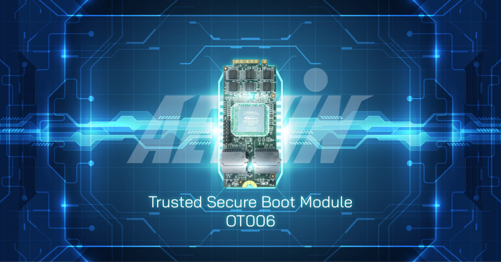
AEWIN Launches the OT006 family of Trusted Secure Boot Module for increased firmware resilience to guard against tampering and data corruption. This is part of AEWIN’s push for a hardware system root of trust for our network and edge computing systems. We have leveraged our experiences from specialized sectors where tamper resistance and firmware hardening are required.
OT006 is a self-contained module and isolated from rest of the system to reduce possible attack surfaces. The on-board logics identify and authenticate firmware digital signatures inside the system. The actions after detection of the anomaly are programmable. The default is sound the buzzer alarm and hold the boot up sequence, then requiring user interaction to correct the firmware and continue the boot process. The module can be programmed to provide automated firmware recovery if desired.
Another critical part of firmware restoration is ensuring there is a pristine golden image as reference. Extra attention was put into ensuring the integrity of the golden image on-board. To prevent tampering of the golden image, updating the image requires a dedicated hardware key along with password. The addition of a hardware key raises another hurdle for potential malicious actors. An added benefit is that is also prevent tampering by physical access, unless they are able to access the physical hardware key.
There are 2 SKUs of OT006, the OT006A and OT006B. OT006A on-board firmware is based on Intel’s Platform Firmware Resilience (PFR) technology, where OT006B is based on AEWIN’s own Trusted Secure Boot code base. The biggest difference between the 2 technologies is the boot sequence, where PFR has a more sequential verification process flow, and AEWIN Trusted Secure Boot have parallelized the verification process to speed up the boot sequence. However, both are designed to offer similar set of features and can secure the firmware on-board and detect if errant hardware has been added.
The OT006 support is being integrated into many of our products. The first wave of the systems supporting the modules has already been announced: BIS-5221 and SCB-1932. Please talk to our friendly sales about integrating firmware security into your next AEWIN devices.
 |
OT006 – Trusted Secure Boot Module |
這篇文章 AEWIN Trusted Secure Boot – OT006 最早出現於 AEWIN。
]]>這篇文章 One Touch Bypass 最早出現於 AEWIN。
]]>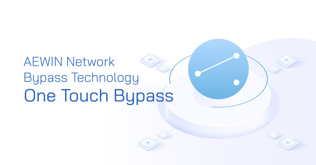
AEWIN is announcing the latest iteration of our network bypass technology, the One Touch Bypass. Internet access is essential to the modern business, where it handle almost every form of communication to the outside world. It has enabled instant interactions across the globe using instant messaging, telephony, and the basic email. Internet connection has become the lifeline of businesses and ensuring access is mission critical. AEWIN One Touch Bypass function allows a system and Network Expansion Module to switch over to bypass-mode as long as the system is receiving power, regardless of whether it is powered on or off. This enhancement comes with the wider adoption of on-board BMC (Baseboard Management Controller).
In a fully functional system, network packets entering the system via LAN1. Packets are processed then sent to downstream device via LAN2. In the event of system unavailability, the BMC and onboard MCU inside the Network Expansion Module works independently of the host system and interconnects LAN1 and LAN2 to allow packets to move straight through, bypassing the system. In failed system without Bypass functionality, it would act as a roadblock to the network connection and sever the critical communication link. By using LAN Bypass equipped systems and Network Expansion Modules, we can pass the packets downstream to route around the failure. This is a cost-effective plan for non-essential network functions, such as those for network optimization, load balancing, or sniffers for network telemetry. For critical network security devices, the Bypass can be used to route the traffic to a redundant device to maintain the security perimeter.
One Touch Bypass is accessed through a physical switch to signal the BMC to initiate the bypass process, and after turning on it will continue to function in this mode even if the host system has been powered off. There are additional modes that can be configured in the MCU, where you can force disconnection with the Drop mode and Link-Loss mode to diagnose network disconnections. With the right setting on the MCU, it can also act as an emergency network disconnect switch to immediately cut off upstream network access in event of severe intrusion or other security violations.
These are useful features to add to the toolkit of network administrators. With years of experience building network appliances, we see the Bypass function as one of the most cost-effective way to add more robustness and resilience to your network. It is invaluable by itself, but in conjunction with system redundancies, it can be a force multiplier that can increase the network resilience several fold.
這篇文章 One Touch Bypass 最早出現於 AEWIN。
]]>這篇文章 OT004 – AEWIN Trusted Secure Boot module 最早出現於 AEWIN。
]]>
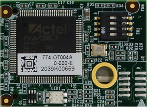
Hardware platforms are getting more and more complex, and as a side effect firmware have been given even more functionalities and controls even more things than before. Thus, it is absolutely essential to maintain the integrity of the on-board firmware to ensure the security of the data passing through the system. AEWIN is experienced in maintaining the integrity of the system due to prior experiences as ODM for specialized sectors.
Today we’ll take a deeper look at our OT004 module that we’ve launched last year. It is the first chain in the root of trust security system we’ve devised to increase the firmware resiliency. OT004 is a self-contained module and isolated from rest of the system to reduce possible attack surfaces. It is equipped with a FPGA with AEWIN Trusted Secure Boot firmware. The on-board logics identify and authenticate firmware inside the system. If an anomaly has been found, it can provide automated firmware recovery or hold the boot sequence and alerting the system admins. The default behavior is programmable and can be adjusted by the administrator during the setup of the module.
To prevent tampering, the golden image stored on-board is locked from changes. Without updating the module, any firmware updates or unauthorized changes will be overwritten and restoring it to the previously known good state. There are several layers of security and algorithms to prevent an attacker from brute-force attacks on the module to compromise the system. Likewise, there module protects itself from attacks and unauthorized updates with several layers of security.
To support the wide range of AEWIN platforms, OT004 module has been split into 3 different SKUs: OT004A, OT004B, and OT004C. OT004A is specifically designed for systems with on-board BMC, such as the SCB-1927 and SCB-1928, AEWIN’s Intel Purley platforms with on-board BMC. With on-board BMC, the root of trust starts at verification of BMC firmware, where it can verify the BIOS image. Which then continues the root of trust until the booting of the OS, where it can verify the operation of AEWIN Trusted Secure Boot module to complete the complete chain in root of trust.
OT004B and OT004C is designed for Intel and AMD system respectively to provide root of trust function starting at the BIOS. It is designed primarily for systems without on-board BMC. Due to the slightly different firmware hardware architecture, it required a split in SKU to support the 2 platforms. For example, SCB-1826 supports the OT004B, and SCB-1833 supports the OT004C. Please let us know if you have any questions or comments about integrate firmware security into your next AEWIN devices. Our friendly sales can help you secure your next AEWIN platform.
Trusted Secure Boot Module
- Trusted Secure Boot Module
- TSB pin header
這篇文章 OT004 – AEWIN Trusted Secure Boot module 最早出現於 AEWIN。
]]>這篇文章 OCP3.0 – The Future Trend 最早出現於 AEWIN。
]]>
Open Compute Project over the years has introduced many interesting ideas into traditionally conservative server space. The OCP form factor network cards has been one of the breakout technologies that found traction outside of OCP OpenRack compliant servers. The OCP3.0 form factor NICs that is trickling into the market is readying the world for beyond 100Gbps connections.
The form factor have advantage over standard PCIe NICs in that it is not perpendicularly mounted in relation to the motherboard, or require a riser that will degrade the signal quality of the stringent PCIe Gen4 and the incoming Gen5 standard. OCP3.0 was ground up designed to take the latest PCIe standard and electrical requirements into consideration, as well as the up coming networking standards beyond 100Gbps. Two form-factors were defined: SFF and LFF, which has PCIe x16 and x32 lanes capability. This allows 200Gbps (QSFP56) and 400Gbps (QSFP56-DD) of bandwidth respectively, future-proofing the form factor for many years to come.
One of the main change from the previous iterations of OCP NICs is that the form factor has evolved from a board-on-board mezzanine to a board-edge format. This has some highly beneficial implications. OCP 2.0 cards has space limitations regarding size of the heatsink. The larger footprint of OCP3.0 allows increase of heatsink surface area to allow better cooling potential, especially critical in server configuration where NIC is mounted toward the hot isle. The board-edge connection allows easier service without opening the server, while also taking advantage of PCIe’s hotplug feature for the ability for hot servicing to reduce downtime. Network card vendors, such as Intel and Mellanox, already have OCP3.0 NICs available in market and we’re expecting wider industry to embrace this form factor.
這篇文章 OCP3.0 – The Future Trend 最早出現於 AEWIN。
]]>這篇文章 PCIe Gen 4 – Exactly what network computing needed and more 最早出現於 AEWIN。
]]>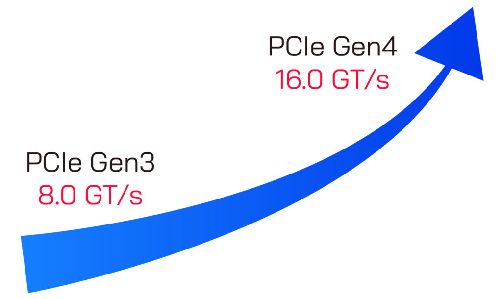
The latest iteration, PCIe Gen 4, has doubled the bandwidth over PCIe Gen 3 to 16GT/s over a single lane. Due to the 128/130bit encoding scheme for parity bits, the true throughput is 1.969 GB/s. a full PCIe x16 lane is capable of nearly 32GB/s throughput, and x8 lane has exactly half. A PCIe Gen 4 x8 link is capable of supporting a 100Gbps ethernet connection without bottlenecks. This is where it is interesting for us as a network computing specialist.
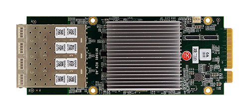
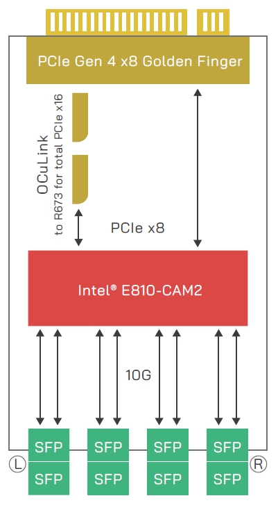
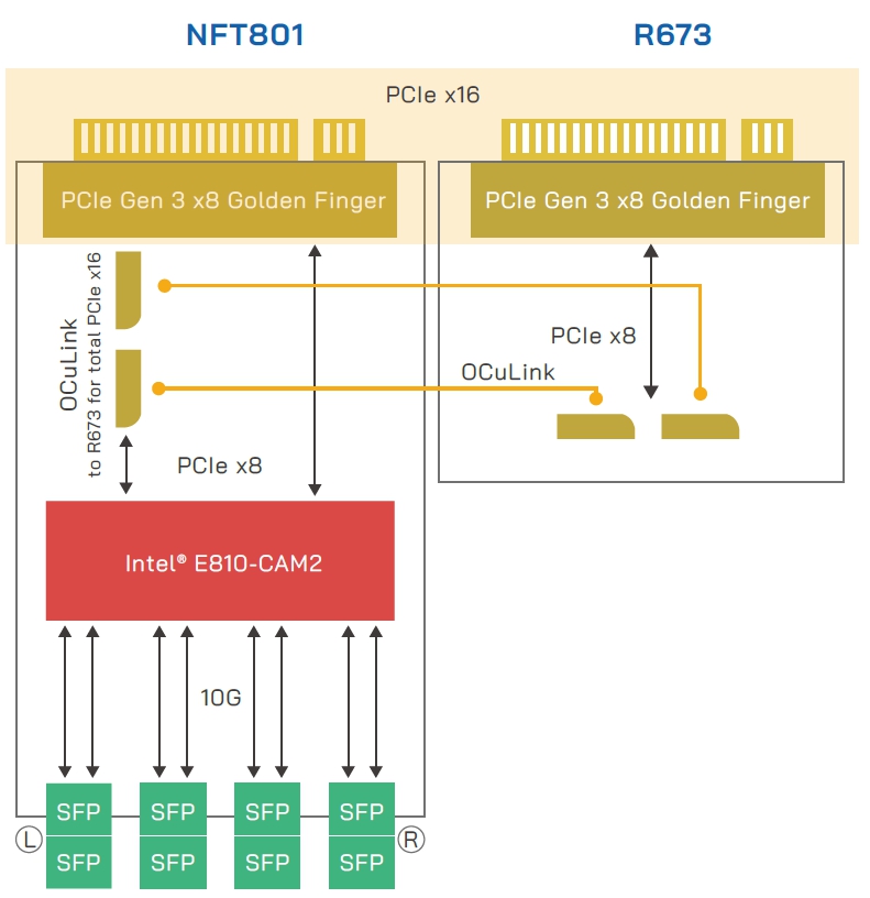
AEWIN’s latest PCIe Gen 4 based network computing platforms are equipped with 8x total PCIe x8 expansion bays to support up to 8x 100Gbps connections with full throughput capabilities with our Intel E810 based R671 expansion modules. Intel E810 is also capable of supporting up to 4x 25Gbps (R672), or 8x 10Gbps (NFT801). Inside our SCB-1932 and 1937, it allows up to 32x 25Gpbs or 64x 10Gbps ports. The increased port density allows up to 32x 10Gbps in 1U space, where previous generation requires up to 2U to satisfy this port configuration. The flexibility of port configuration allows our users to configure the system to tailor it for their exact networking needs.
Beyond networking, PCIe Gen 4 has great potential for accelerated computing. Although bandwidth through the PCIe connection is generally not an issue for GPU accelerated computing, being able to transfer the same amount of data in shorter time will ensure that GPU utilization will be maximized and never waiting for data.
|
NFT801
|
|
|
NFT801
|
|
|
NFT801+R673 for total PCIe x16
|
這篇文章 PCIe Gen 4 – Exactly what network computing needed and more 最早出現於 AEWIN。
]]>這篇文章 Current State of Solid-State Storage 最早出現於 AEWIN。
]]>
Spinning drives and fans are the 2 major sources of potential failures inside an otherwise reliable system. Replacing the traditional spinning drives will move the overall system-reliability up another notch. SSDs are not only more reliable, but generally faster in both ultimate read/write performance as well as access latencies which results to more responsive systems. There is plethora of choices of solid-state drives, and we’ll quickly look go through the interfaces and form factors that stuck around, and those that didn’t.
Definition
We will primarily look at SSDs. We’ll quickly discuss eMMC/DOM/CF/other simple flash based drives and cards here as they do not include an advanced drive controller, hampering performance and longevity of the on-board NAND flash. They are diminutive disks primarily designed for embedded use to hold OS images. The read performance varies from ok to slow, but the main concern is the slower write speeds and lowered write endurance. It is recommended for use in applications for highly read focused workloads.
Interface specification and what came before
We previously look at some of these connectors in more detail. Please hop on over if you have interest <link: https://www.aewin.cn/application/internal-data-connectors/ >
We won’t go into detail here, but there are 3 more popular interfaces for attaching SSDs to host systems, and they are: SATA, SAS, and PCIe. SATA and SAS have long history of being used for storage. PCIe direct attached storage is a recent thing and has went through some trial and error until its current state. Although NVMe became synonymous with PCIe based SSDs, there were others that came before that never caught on. AHCI based PCIe drives were introduced before NVMe. AHCI was a logical interface designed for legacy spinning disks and could not take advantage of the extra speeds offered by SSDs. NVMe rescued us from the woefully inadequate AHCI standards by defining a standard from the ground up that aims to take advantage of extensible nature of PCIe as well as ever improving speeds of NAND flash-based drives and its controller. NVMe is a logical interface and can be carried in many form factors.
Form Factors
|
SSD |
Interface | PCIe Interface used | ||||
| SATA | SAS | PCIe | NVMe | AHCI | ||
| Form Factor | 2.5″ | V | V | V (U.2) | V | V |
| M.2 | V (B or B+M Key) | X | V (M Key) | V | V | |
| PCIe card | X | X | V | V | V | |
| mSATA | V | X | X | N/A | N/A | |
| EDSFF | X | X | V (E1/ E3) | V | X | |
| NF1 | X | X | V (NGSFF/M.3) | V | X | |
| SATAe | X | X | V | V | V | |
Note: Type of interface used for PCIe based SSD
Red = outdated format
mSATA
mSata is a miniaturized SATA drive, hence the name: micro-SATA. It is a popular format for embedded usage due to its smaller footprint. It has uses the PCIe mini connector and form-factor, but electrically uses the ubiquitous SATA interface, allowing it to be used in wide variety of platform.
M.2
M.2 is commonly what people think of solid-state drives today. It comes in many standard lengths, such as 22110, 2280, 2242, 2230, and 2224. It can be mounted parallel to the motherboard to allow lower height installation or mounted perpendicular to the motherboard in the case of the shorter drives. Parallel mounting does takes up valuable space on the PCB, whereas perpendicular has smaller footprint requirements. The trade-off is the lower density on the smaller drives usually used in this mounting. Longer drives may be perpendicularly mounted but is less secure and may require additional mechanical aids to affix it to the system.
One disadvantage of M.2 is thermal related. Majority of the M.2 is offered as bare PCB + chip without cooling solution on it. Without cooling, it is more likely to hit thermal limits in IOPS heavy workloads. It is potentially more fragile to physical forces or static discharge while handling without any barrier from touching bare PCB or components. On the other hand, this make it a compact solution that is 22mm wide that can easily squeeze into many places. Some systems may also use PCIe x2 lanes to the M.2, which limits the ultimate bandwidth to the M.2. If you require full bandwidth for the M.2, this is an area that should be specifically looked at.
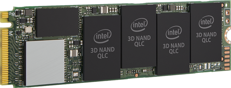 Picture originates from Intel
U.2
U.2 is a 2.5” drive form factor with PCIe x4 connection. It can be configured as 1x PCIe x4, or in special dual port drives, 2x PCIe x2 connections to increase redundancy in routing the data connection. It is available in 7mm, 9mm and 15mm thickness, with the higher performance drives typically in 15mm. This has long been the standard in datacenter focused SSD. The host receptacle is compatible with 2.5” SATA and SAS drives, and offer data and power through the same port.
Intel Ruler
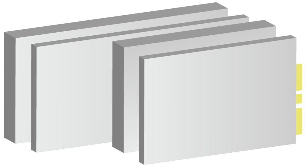
Intel Ruler is a slightly complicated topic, so we’ll just go over the overview today. Intel ruler is officially named EDSFF, Enterprise & Datacenter Storage Form Factor. It aims to replace the M.2 form-factor by aiming at the weakness of M.2. EDSFF has long variants that allows more NAND chips onboard for drastically increased capacity. On the other end, there are the E1.s short form factor that is small, but also install parallel to the motherboard, but with the slim edge toward the motherboard. This allows highest density and lower footprint on the host board. This also allows the form factor to be front mounted in a high-density configuration, limited by only the number of PCIe lanes available. It also took a page out of the Samsung NF1 playbook by increasing the width of the drives to increase NAND density.
|
|
|
 |
PCIe HHHL
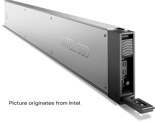
PCIe add-on card form factor is likely the highest performing solid-state drives. It can offer PCIe x8 and x16 connection host, increasing the bandwidth. The class of controller used in these drives are typically higher performance as well to support the higher bandwidth. The form factor of the drive also allows larger heatsinks to keep the drive operating in top performance mode without degradation. The flipside of the coin to that performance is that it requires so many PCIe connections, limiting the number of drives that can be added. In a typical server class application, there are also limited number of slots, which are typically better used for other hardware, such as 100GbE NICs or accelerators. Only in very specialized cases that these make sense, such as large databases that require IOPS that couldn’t be achieved with another class of hardware.
Picture originates from Intel
Honorable mentions:
Samsung NGSFF/NF1 (“M.3”)
We would be remiss if we did not talk about the NF1. NF1 has some interesting feature of note, such as Dual Port capability NF1 for additional resilience for hardware faults, similar to dual port U.2. It examined the bottleneck of M.2 (the width) and expanded the width to allow higher density NAND modules to fit onboard. It also uses the same M-key M.2 connector, allowing hardware vendors to stock 1 less item… However, this is where the trouble starts. NF1 is electrically incompatible with M.2 while using the same connector. Worse yet, due to the pinout, it is possible to short some data pins to ground due to the different pin define. M.3 pin define is ill-thought through and fortunately Samsung has joined onboard with Intel’s EDSFF to avoid all the potential troubles this standard may cause.
SATAe
SATAe (SATA express), not to be confused with eSATA (external SATA), is a confusingly branded standard introduced in SATA 3.2 specification which used 2x side-by-side SATA connectors to carry PCIe signal. It was a form-factor that aimed to leverage the SATA connectors while allowing backwards compatibility on the host end to support 2x SATA drives. It was a big and cumbersome connector that industry is glad that never caught on.
這篇文章 Current State of Solid-State Storage 最早出現於 AEWIN。
]]>